
Troubleshooting Prisma Daps
Select to view the instructions for the wiring used
| Error | Action |
|---|---|
| Out of function Nothing happens when you press on the push front No light No sound |
Check that the power supply is available on: (I/O-terminal 10* and 11*) Other models Check that power supply is available on RED (I/O-terminal 4* and 5*) and GREEN (I/O-terminal 6* and *5) phases respectively. If available: Check the fuses with ohm meters and replace the blown ones with the correct mA number. If both the power supply and fuses are OK, replace the Prisma Daps unit and send the broken one to PrismaTibro. |
| Red light on the LED lens in front | Check that lamp power supply is available on: I/O-terminal 4,5 and 6* Reset the power supply: Disconnect wire 10* and 11*, and reconnect again. |
| No locating sound No sound during either RED or GREEN phases |
• Does it work to push the front but without notification sound, then check the loudspeaker • Is it mechanically complete? • Is the magnet in place? • Does ohm measurement across the loudspeaker provides about 6-10 ohms? • Is the night option on? • Is there any power supply between I/O-terminal 21* and 5*? |
| Locating sound during RED phase only | Check incoming power supply on GREEN phase: I/O-terminal 5* and 6*. If the power supply is available, then replace the Prisma Daps unit and send the broken one to PrismaTibro. |
| Vibrator out of function | Make sure the cable is connected to the card. In older models, there is a fuse that needs to be checked or replaced, located right next to the connector of the vibrator. |
| LED lens in front and LED light ring lights or flashes when it should not | Check the power supply between blue and brown wire to the electronic module.
If the voltage is higher than 120 V, there is a power leakage from the traffic control or the power is induced due to poor cabling in the infrastructure, In such case load resistors to be mounted in the traffic control. Prisma Daps 2000•L and Prisma Daps 2000•M can also be completed with load resistor cards that can easily be mounted next to the electronic modules. Contact PrismaTibro for more info. |
| The problem still exists | Activate the configuration file you received upon supplying the product from factory and make sure if the experienced error still exists. If the problem still exists contact PrismaTibro support. |
| Other errors | Contact PrismaTibro support: support@prismatibro.se |
*I/O-terminal is a screw terminal number on the electronic module
Tools
• Voltmeter
• Prisma Daps App, works on Android smartphone or tablet
| Error | Actions |
|---|---|
| Out of function Nothing happens when you press on the push front No light No sound |
Check that the power supply is available on: (I/O-terminal 10* and 11*) Other models Check that power supply is available on RED (I/O-terminal 4* and 5*) and GREEN (I/O-terminal 6* and *5) phases respectively. If available: Check the fuses with ohm meters and replace the blown ones with the correct mA number. If both the power supply and fuses are OK, replace the Prisma Daps unit and send the broken one to PrismaTibro. |
| Red light on the LED lens in front | Check that lamp power supply is available on: I/O-terminal 4,5 and 6* Reset the power supply: Disconnect wire 10* and 11*, and reconnect again. |
| No locating sound No sound during either RED or GREEN phases |
• Does it works to push the front but without notification sound, then check the loudspeaker • Is it mechanically complete? • Is the magnet in place? • Does ohm measurement across the loudspeaker provides about 6-10 ohms? • Is the night option on? • Is there any power supply between I/O-terminal 21* and 5*? |
| Locating sound during RED phase only | Check incoming power supply on GREEN phase: I/O-terminal 5* and 6*. If the power supply is available, then replace the Prisma Daps unit and send the broken one to PrismaTibro. |
| Led in front, no light Led Light Ring, no light |
Check the power supply between blue and brown wire to the electronic module.
If the voltage is higher than 120 V, there is a power leakage from the traffic control or the power is induced due to poor cabling in the infrastructure, In such case load resistors to be mounted in the traffic control. Prisma Daps 2000•L and Prisma Daps 2000•M can also be completed with load resistor cards that can easily be mounted next to the electronic modules. Contact PrismaTibro for more info. |
| The problem still exists | Activate the configuration file you received upon supplying the product from factory and make sure if the experienced error still exists. If the problem still exists contact PrismaTibro support. |
| Other error | Contact PrismaTibro support: support@prismatibro.se |
*I/O-terminal is a screw terminal number on the electronic module
Aid
• Voltmeter
• Prisma Daps App, works on Android smartphone or tablet
Error Detection Function
- The error detection is always ON.

- To activate red light on the LED in front in the event of an error, dip-switch 6 must be switched ON.
- Red light on the LED in front constantly lights up all the time the error persists.
When the error is fixed, the red LED on the front goes off and the unit automatically cancels all error signals.
Optical error detection for service technicians
- In the event of an error, the optical error signal for service technicians is always switched on.
- To access the optical error signal for service technicians, unscrew the top cover which is connected to the LED light ring and push up the front at least 5 cm.
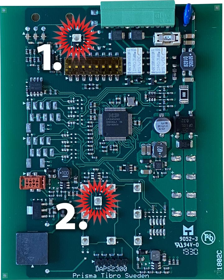
See the photo here next to motherboard, explanation:
1. Error signaling for service technicians
2. Error signaling with red LED notification in front - In the event of an error, the upper red LED flashes 5 times in a sequence.
The sequence is repeated every 10 seconds as long as the error persists.
The flashes represent the possible failure of the functions below in the following order:
Short flash represents
that no error has been detected on the respective function.
Long flash represents
that an error has been detected on the respective function.
| LONG FLASH INDICATES ERROR ON FUNCTION | FUNCTION WITH ERROR | MEASURE |
|---|---|---|
| Flashing 1, long | Relay 1 | Replace the voltage adapter |
| Flashing 2, long | LED notification in front | Replace the motherboard |
| Flashing 3, long | LED Light Ring | Check the connection. If properly connected: replace the LED Light Ring. |
| Flashing 4, long | EEPROM | Replace the motherboard |
| Flashing 5, long | Push front | Replace the motherboard |
Requirements
- To be able to send an error signal to the controller, the Prisma Daps 2300 must be powered from a constant power source as any error signal is made at the beginning of each new green phase as long as the error persists.
- If the unit is equipped with a LED Light Ring, the LED Light Ring must be connected.
Error Detection Function
- The error detection is always ON.
- To activate red light on the LED in front in the event of an error, dip-switch 6 must be switched ON.
- In case of errors, Prisma Daps 2300•S sends a 5-second voltage pulse to the controller via the white wire every time green phase is initiated.
Red light on the LED in front constantly lights up all the time the error persists.
When the error is fixed, the red LED on the front goes off and the unit automatically cancels all error signals.
Optical error detection for service technicians
- In the event of an error, the optical error signal for service technicians is always switched on.
- To access the optical error signal for service technicians, unscrew the top over which is connected to the LED light ring and push up the front at least 5 cm.
See the photo here next to motherboard, explanation:
1. Error signaling for service technicians
2. Error signaling with red LED notification in front - In the event of an error, the upper red LED flashes 5 times in a sequence.
The sequence is repeated every 10 seconds as long as the error persists.
The flashes represent the possible failure of the functions below in the following order:
Short flash represents
that no error has been detected on the respective function.
Long flash represents
that an error has been detected on the respective function.
| LONG FLASH INDICATES ERROR ON FUNCTION | FUNCTION WITH ERROR | MEASURE |
|---|---|---|
| Flashing 1, long | Relay 1 | Replace the voltage adapter |
| Flashing 2, long | LED notification in front | Replace the motherboard |
| Flashing 3, long | LED Light Ring | Check the connection. If properly connected: replace the LED Light Ring. |
| Flashing 4, long | EEPROM | Replace the motherboard |
| Flashing 5, long | Push Front | Replace the motherboard |
Requirements
- To be able to send an error signal to the controller, the Prisma Daps 2300 must be powered from a constant power source as any error signal is made at the beginning of each new green phase as long as the error persists.
- If the unit is equipped with a LED Light Ring, the LED Light Ring must be connected.
Error Detection Function
- The error detection is always ON.
- To activate red light on the LED in front in the event of an error, dip-switch 6 must be switched ON.
- In case of errors, Prisma Daps 2300•S sends a 5-second voltage pulse to the controller via the white wire every time green phase is initiated.
Red light on the LED in front constantly lights up all the time the error persists.
When the error is fixed, the red LED on the front goes off and the unit automatically cancels all error signals.
Optical error detection for service technicians
- In the event of an error, the optical error signal for service technicians is always switched on.
- To access the optical error signal for service technicians, unscrew the top over which is connected to the LED light ring and push up the front at least 5 cm.
See the photo here next to motherboard, explanation:
1. Error signaling for service technicians
2. Error signaling with red LED notification in front - In the event of an error, the upper red LED flashes 5 times in a sequence.
The sequence is repeated every 10 seconds as long as the error persists.
The flashes represent the possible failure of the functions below in the following order:
Short flash represents
that no error has been detected on the respective function.
Long flash represents
that an error has been detected on the respective function.
| LONG FLASH INDICATES ERROR ON FUNCTION | FUNCTION WITH ERROR | MEASURE |
|---|---|---|
| Flashing 1, long | Relay 1 | Make sure that the brown and black wires are connected together. If they really are: replace the electronic module. |
| Flashing 2, long | LED notification in front | Replace the motherboard |
| Flashing 3, long | LED Light Ring | Check the connection. If properly connected: replace the LED Light Ring. |
| Flashing 4, long | EEPROM | Replace the motherboard |
| Flashing 5, long | Push Front | Replace the motherboard |
Send e-mail
here if you wish PrismaTibro support to contact you, or call +46 504 400 40